Recognising and drawing circuit symbols
FREE PHYSICS REVISION · UNIT 3 · C1.1
Pearson BTEC Level 3 AAQ Applied Science · Issue 7 (May 2026)
Learning objectives
- Recognise the circuit symbols used for sources, switches, lamps, resistors, meters and the semiconductor components in this lesson.
- Draw circuit diagrams using standard symbols and clear connections.
- Distinguish connected junctions from wires that cross without joining.
- Interpret a circuit diagram to identify its components and their intended roles.
Specification mapping: C1.1
Prerequisites: Start here; basic arithmetic and SI notation.
Physical principles
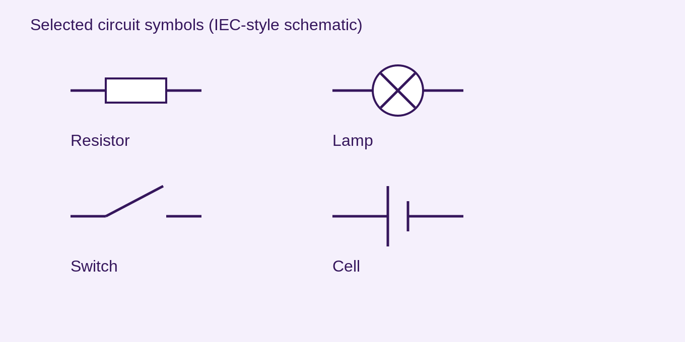
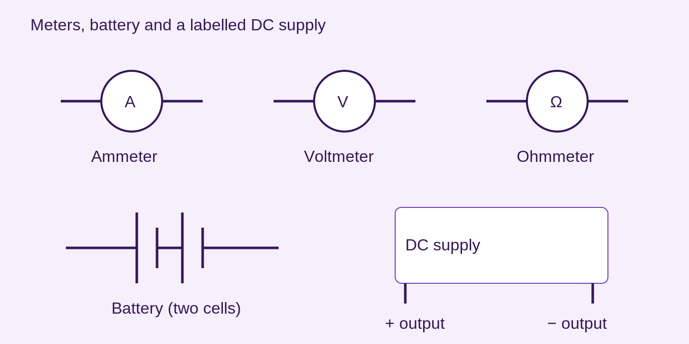
A circuit diagram represents electrical connections rather than the physical positions of components. Use standard symbols and straight connecting wires; a junction dot means wires connect. Where wires cross without connection, make the absence of a junction clear. A cell has one long and one short parallel plate; the long plate is positive. A battery uses more than one cell pair.
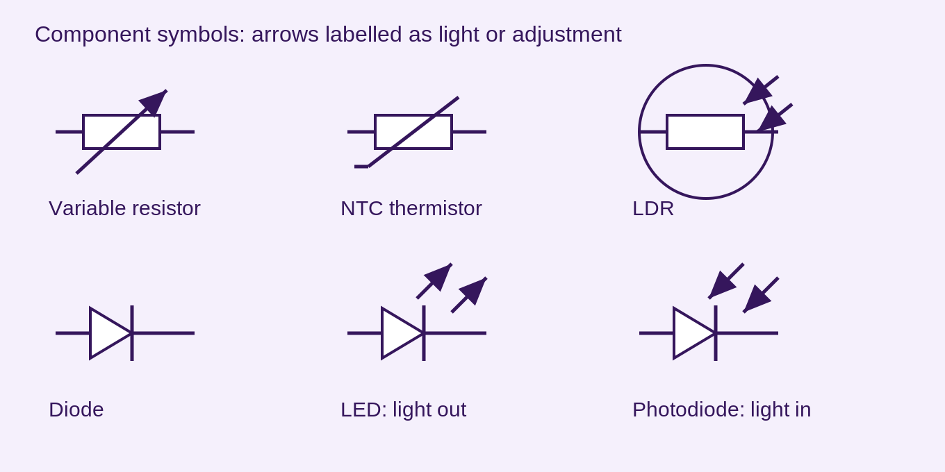
In common IEC notation a fixed resistor is a rectangle. A lamp is a circle with a cross. A variable resistor adds a diagonal arrow across the resistor. An open switch shows separated contacts; closing it completes the path. An ammeter is a circle marked A, a voltmeter V and an ohmmeter Ω. A supply may be labelled with voltage and polarity rather than drawn as a cell.
A diode symbol has an anode side and a cathode bar; current is readily conducted forward from anode towards cathode under suitable conditions. An LED adds arrows pointing outwards to represent emitted light. A photodiode has light arrows pointing inwards. An LDR has incoming light arrows directed at a resistor, commonly within a circle. A thermistor uses a resistor with its characteristic temperature-dependent marking; label NTC where that behaviour is intended.
Correct topology matters as much as symbol recognition. A meter symbol that looks right but is placed across a supply when it should be in series gives the wrong circuit and may be unsafe. Label ambiguous or unfamiliar components rather than inventing symbols.
Scientific diagram and interpretation

Worked examples and applications
Cell polarity
The longer cell plate is positive. Conventional current leaves this terminal around an external resistive circuit, while electron drift in a metal is in the opposite direction.
Light arrows
An LED’s arrows point away from the diode; a photodiode’s arrows point towards it. These arrows denote light, not conventional current direction.
Common misconceptions
Light arrows and diode polarity marks serve different purposes. A crossing is not automatically a connected junction.
Examination technique
Use a ruler, identify junctions and label supply polarity and meter type.
For an explanation, connect the physical cause to its effect. For a calculation, state the model, rearrange before substitution, retain intermediate digits, and finish with units. For a data question, refer to the actual readings and distinguish a trend from proof of a cause.
Check your understanding
Five questions. Choose an option, then Check Answer. Read the feedback and use Try Again to reset. Use Tab between controls, arrow keys within radio groups, and Enter or Space on buttons. These local practice answers are not saved.
Take Your Learning Further
Practise
Build Your Confidence
Reinforce your understanding with our topic-based workbook. Every workbook page links back to its matching online lesson, so you can revisit explanations whenever you need support.
Explore Workbook – PhysicsMaster
Get Exam Ready
Apply your knowledge with exam-style practice papers and detailed mark schemes. Identify what you’ve mastered and what to revise next.
Practice Papers – PhysicsEXAM RESOURCES
Physics exam resources
Apply your knowledge with written practice.
Browse exam resources